Electric vehicle (EV) platforms stand at a critical juncture of high voltage, immense power, and stringent safety protocols. From the intricate battery packs and powerful traction inverters to rapid DC fast chargers and complex cable harnesses, engineers face the demanding task of rigorously proving insulation integrity throughout the development phase and at the crucial end-of-line production stage. This vital verification process is precisely where high-potential testing, often referred to as hipot testing, becomes an indispensable tool.
Hipot testing encompasses two primary methodologies: withstand tests and breakdown tests. In a withstand test, a product is intentionally subjected to voltages significantly higher than its normal operating conditions, while engineers meticulously measure any resulting leakage current. Conversely, a breakdown test systematically increases voltage until the insulation fails, a process critical for establishing safe design margins for the component.
Both testing approaches demand precise control over kilovolt sources, highly sensitive measurement of exceptionally low leakage currents, and robust, safe discharge pathways. This comprehensive guide delves into the methodologies for constructing reliable hipot stages tailored for EV testing and elucidates why high-voltage reed relays are ideally suited for the essential switching and safety functions within these sophisticated testing setups.
Key Takeaways
- EVs require rigorous high-potential (hipot) testing to ensure insulation integrity and operational safety across all high-voltage components.
- Hipot testing involves both withstand tests, measuring leakage at elevated voltages, and breakdown tests, identifying insulation failure points.
- High-voltage reed relays offer superior performance for hipot switching due to their sealed contacts, extremely low leakage, high insulation resistance, and galvanic isolation.
- Unlike electromechanical or solid-state relays, reed relays maintain measurement fidelity, crucial for detecting microampere to nanoampere leakage currents in EV systems.
- Proper hipot stage architecture with reed relays is essential for source routing, accurate measurement, safe discharge, and reliable protection interlocks.
- Selecting the right reed relay involves considering standoff voltage, switching capability, coil isolation, insulation resistance, and operational speed.
- Implementing design best practices like energy-based considerations, guarded layouts, and temperature validation enhances the effectiveness and safety of EV high-potential testing.
The Imperative of High-Potential Testing in EV Manufacturing
The proliferation of electric vehicles has brought with it an unprecedented focus on electrical safety. The very nature of EV powertrains, which operate at elevated voltages, mandates meticulous attention to insulation quality to prevent short circuits, electrical shocks, and potential thermal events.
High-potential testing serves as the ultimate arbiter of insulation soundness, confirming that components can safely withstand the electrical stresses they will encounter in real-world operation. Its role extends beyond mere compliance, embedding a fundamental layer of trust and reliability into every EV manufactured.

Critical Applications Across EV Components
The necessity for robust EV high-potential testing spans various critical components within an electric vehicle’s ecosystem, each presenting unique challenges and requirements for the hipot station.
Battery Modules and Packs
For battery modules and complete packs, hipot testing verifies isolation from the vehicle chassis, mitigating the risk of electrical hazards. It also scrutinizes potential coolant ingress risks and validates the integrity of contactor assemblies and pre-charge networks. End-of-line stations typically execute DC withstand tests, archiving leakage results to establish a vital baseline for future field service and diagnostics.
Traction Inverters and DC-Link Assemblies
Traction inverters, responsible for converting DC battery power to AC for the electric motor, along with their associated DC-link assemblies, require validation of the critical isolation barrier separating the high-energy DC bus from sensitive control electronics. These tests are often repeated after undergoing thermal cycling or vibration stress to simulate real-world operational conditions.
Onboard Chargers and DC Fast Chargers
Onboard chargers and high-power DC fast chargers demand confirmation of robust isolation from the AC grid and between their various power stages. For megawatt-class charging systems, ensuring safe discharge after a test step is paramount. This allows operators to safely connect the subsequent unit under test without risk of residual stored energy.
High-Voltage Wiring Harnesses and Connectors
Cable hipot checks are essential for detecting pin-to-pin shorts and measuring pin-to-shield leakage, often across hundreds of nets routed through sophisticated switching matrices. These components are the arteries of the EV’s electrical system, and their integrity is non-negotiable for overall system safety and performance.
In all these diverse use cases, the core requirements imposed on the hipot station remain consistent: the ability to apply and precisely measure at kilovolt levels, to limit fault energy, to safely sequence tests, to minimize overall test time, and, crucially, to maintain the unwavering trustworthiness of leakage current measurements.
The Role of Switching Technology in Hipot Accuracy
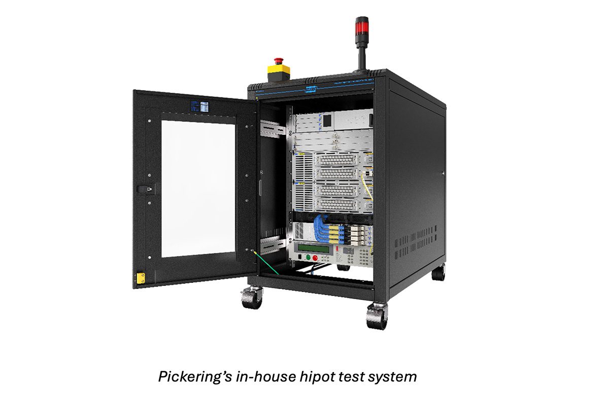
At the heart of most hipot test rigs lies a sophisticated arrangement comprising a programmable high-voltage (HV) source, advanced measurement and protection hardware, and a critical bank of switches. These switches are responsible for routing the HV source and meter to the unit under test (UUT) or to a designated discharge load. The performance of these switches is pivotal, as they shoulder several demanding responsibilities simultaneously.
Firstly, the switches must possess the inherent capability to withstand high open-circuit voltages without succumbing to breakdown. Secondly, they need to reliably switch the specified voltage and energy levels when commanded. Thirdly, it is imperative that these switches contribute minimal leakage current and parasitic capacitance to the measurement path, which could otherwise distort true UUT readings. Fourthly, they must provide robust galvanic isolation between the high-voltage domain and the sensitive control electronics. Finally, fast and repeatable operation over extensive duty cycles is essential for maintaining efficient test throughput.
Why High-Voltage Reed Relays Excel
Electromechanical relays (EMRs) are often considered for their affordability, but their open-air contacts inherently limit the practical switching voltage and standoff capabilities. Solid-state relays (SSRs), while offering speed and compactness, often introduce non-linear leakage currents and higher off-state capacitance. These characteristics can inadvertently mask genuine leakage issues within the device under test, leading to potential false passes or failures.
High-voltage reed relays, however, address a distinct set of challenges with remarkable efficacy. Their contacts are hermetically sealed within an inert vacuum or gas-filled glass envelope. This design allows them to tolerate significantly higher electric fields within a remarkably compact package, delivering exceptionally low off-state leakage with minimal parasitics. The coil, which controls the switch, is galvanically isolated from the signal path, providing a crucial layer of protection for delicate control electronics.
Furthermore, their operate times are impressively short, typically under a millisecond. This rapid response directly contributes to minimizing overall test cycle times in high-volume production environments. In essence, a high-voltage reed relay behaves almost as an ideal open or closed conductor, a characteristic that is absolutely vital when conducting highly sensitive measurements in the microampere or even nanoampere range.
Comparative Performance: Leakage Current Analysis
A graphical comparison of leakage current versus isolation voltage clearly illustrates the performance disparity across various switch classes. Traditional EMRs exhibit an early rise in leakage and are constrained by their comparatively lower standoff voltages. Typical high-voltage SSRs maintain their integrity for longer but still demonstrate leakage currents in the microampere region as the applied voltage increases.
In stark contrast, instrument-grade reed relays maintain significantly lower leakage levels even at elevated voltages. This superior performance is attributable to their insulation resistance, which is orders of magnitude higher—typically in the 10¹² to 10¹³ ohm range for standard devices, and extending up to an extraordinary 10¹⁴ ohm in custom-engineered builds. For the stringent hipot testing required for EV battery packs, inverters, and chargers, this difference in leakage performance can be the decisive factor between accurately identifying a clean pass and misdiagnosing a false failure.
Architectural Considerations for EV Hipot Stages
A robust and practical EV high-potential testing station integrates several relay-controlled pathways, each serving a specific and critical function to ensure precision and safety.
Source Routing: This path selects the desired voltage domain for testing, such as isolating the pack positive from the chassis, the pack negative from the chassis, or performing pin-to-pin checks on a wiring harness. Reed relays with high standoff ratings serve as the primary isolation elements here, ensuring that only the intended test voltage reaches the UUT.
Measure Path: This circuit switches the sensitive meter across the device under test or directs it to a reference load for self-calibration. The intrinsically low leakage and minimal capacitance of reed relays are crucial in this path, preserving the fidelity and accuracy of the delicate leakage current measurements.
Discharge and Bleed: Following the completion of a test step, it is imperative to safely remove any stored energy. This path routes a resistor across the output, rapidly discharging the UUT. Employing a dedicated reed relay for this function ensures a predictable, reliable, and safe discharge pathway every single time, protecting both equipment and personnel.
Protection and Interlock: Separate relays are often employed to enforce crucial safety permissives. For instance, they can instantly open the source path if a predefined limit current is exceeded, or latch the entire system until a full discharge cycle is confirmed. This adds a vital layer of redundancy and safety to the entire testing process.
Given their compact form factor and inherent magnetic screening, numerous reed relay channels can be densely packed onto a single circuit board. This capability allows for the creation of highly scalable harness or battery pack fixtures, crucial for efficient production testing. For situations demanding Kelvin measurements within the station, two-pole reed relay devices can significantly reduce the required channel count for four-wire connections, optimizing space and complexity.
Selecting the Optimal Reed Relay for EV Applications
When specifying relays for high-potential switching in EV applications, careful consideration of several key parameters is essential to ensure both performance and safety.
The minimum standoff voltage represents the open-contact survival capability, indicating the maximum voltage the relay can withstand across its open contacts without breakdown. For demanding EV and charger applications, devices offering 5 kV, 10 kV, or even 20 kV ratings provide ample safety headroom. The maximum switching voltage and power are critical for breakdown tests and controlled discharge scenarios, ensuring the relay can reliably switch the intended voltage and energy without contact degradation.
Switch-to-coil isolation is a vital parameter that protects sensitive control electronics in the event of a fault in the high-voltage path. Some customizable series, for example, can be configured for up to 25 kV switch-to-coil isolation. Insulation resistance is another crucial specification; higher values directly correlate with superior leakage fidelity. Standard high-voltage reed relays are typically tested to achieve greater than 10¹² ohm, with custom parts capable of reaching over 10¹⁴ ohm. Furthermore, fast operate and release times are important, as quicker operation reduces test dwell time, and faster release shortens the interval from discharge to the system being ready for the next test. Finally, the physical format and shielding of the relays are important considerations, especially when scaling to large matrices. Internal mu-metal shields allow for side-by-side packing with minimal magnetic interaction, preserving signal integrity in dense configurations.
Tailored Product Solutions for EV Hipot Demands
A diverse range of reed relay families can effectively form the backbone of most EV hipot matrices, offering specialized solutions for varying application requirements.
The Series 63 and the customizable Series 600 are ideal for applications demanding the highest isolation, offering up to 20 kV standoff and switching up to 12.5 kV with a maximum power of 200 W. The Series 600 further provides modular options for voltage, coil, shielding, and mounting, and can be configured for exceptional 25 kV switch-to-coil isolation. These are well-suited for battery pack and charger isolation tests, inverter barrier validation, and long-duration burn-in applications where a substantial standoff margin is beneficial. Both series also include changeover options for applications up to 2.5 kV switching and 5 kV standoff.
For high-voltage routing in space-constrained environments, the Series 60 and 65 are excellent choices, providing up to 12.5 kV switching and 15 kV standoff. They handle switch currents up to 3 A at 50 W and carry currents up to 3.5 A, making them frequently utilized in cable and harness hipot fixtures. The compact Series 104 devices, with 5 kV standoff and 1.5 kV switching, are highly useful as measurement selectors, for controlling discharge paths, or as integral safety interlocks within the test rig.
When higher current discharge networks or stress steps are required, the Series 67 and 68 offer high-power capabilities, delivering 200 W switching in a dense package with up to 10 kV standoff and 7.5 kV switching. Their unique design also facilitates higher-density packing while maintaining appropriate pin-to-pin distances. Changeover options are also available for these series, up to 2.5 kV switching and 5 kV standoff. For compact boards requiring up to 3 kV standoff and 1 kV switching, the Series 119 and its surface-mount counterpart, Series 219, enable dense multi-channel fixtures suitable for modular testers. Furthermore, for topologies demanding two-pole parts to support Kelvin connections, a wide range of configurations is available to effectively reduce channel count.
Practical Design Principles for Efficient Hipot Testing
Implementing effective EV high-potential testing requires adherence to several practical design principles that can significantly enhance safety, accuracy, and operational efficiency on the test bench.
Firstly, it is crucial to think in terms of energy, not solely voltage. A 5 kV breakdown step into a capacitive load stores a substantial amount of energy that must be discharged safely. Therefore, the discharge relay and resistor must be appropriately rated for both voltage and the anticipated pulse energy to prevent damage and ensure safety. Secondly, to maintain measurement integrity, it is vital to guard your measurements. This involves using guarded layouts and selecting high-resistance materials around the relay pins to prevent leakage paths from bypassing the meter, thereby ensuring that only the UUT’s leakage is measured. Internal shields within relays can also help mitigate external clearances that might otherwise limit open-contact voltage in some designs.
Thirdly, rigorously sequence for operator safety. This means interlocking the high-voltage source path with the discharge path and incorporating physical door switches or other safety interlocks. Utilizing the fast operate and release times of reed relays can significantly shorten the ‘safe-to-touch’ interval between testing units under test, improving workflow without compromising safety. Finally, it is highly recommended to validate at temperature. Both leakage and standoff characteristics can be sensitive to temperature variations in many systems. Conducting a thorough design validation that sweeps across the operational temperature range with the chosen relay set is critical before finalizing the Bill of Materials (BOM) to ensure reliable performance under all conditions.
Enhancing Production Throughput and Reliability
The success of electric vehicle programs hinges significantly on throughput. In high-volume manufacturing, cycle time and overall system uptime are as critical as the headline voltage ratings of the test equipment. High-voltage reed relays contribute positively on both these fronts.
Their sub-millisecond operate times ensure that the routing steps within a test sequence do not become the dominant factor in the overall test duration, thereby keeping cycle times short and efficient. Furthermore, the mechanical life of these relays can extend to millions, or even billions, of operations when utilized within their specified ratings. This exceptional longevity keeps test fixtures in continuous service, substantially reducing maintenance requirements and associated downtime. The inherently low coil power consumption of reed relays also aids in the thermal design of dense test racks, preventing overheating and contributing to system stability.
For engineering teams aiming to standardize their testing processes across multiple EV platforms, the consistency offered by specific reed relay families is a significant advantage. The same relay types can be reliably deployed in battery pack hipot stations, charger isolation checks, inverter barrier validations, and cable harness testers. This standardization simplifies spare parts management, streamlines documentation, and allows for the reuse of proven, known-good circuit layouts, leading to more efficient development and deployment.
Navigating Your EV Hipot Solution
When embarking on the design or refurbishment of an EV high-potential testing station, making informed component choices is paramount. A pragmatic starting point for primary isolation paths would typically involve one of the Series 63 or Series 600 devices, selected for their robust isolation capabilities. For critical measurement and interlocking functions, the Series 104 offers reliable performance in a compact form factor. Where higher power discharge control is necessitated, the Series 67 or 68 are excellent considerations.
For compact harness fixtures where density is a key design constraint, the Series 119 or 219 are ideal choices. Should your specific topological requirements demand two-pole parts, a comprehensive range of configurations is available to support Kelvin connections and optimize channel count. Importantly, if a catalog device does not precisely meet a unique design constraint, specialized engineering teams can customize parameters such as coil voltage, shielding, pinout, and isolation levels to align perfectly with specific design rules. Expert reed relay engineers are readily available to assist with part selection, provide guidance on creepage and clearance considerations for your circuit board, and offer advice on discharge sizing and safety interlocks tailored to your specific voltage and energy requirements, ensuring a robust and compliant EV hipot solution.
Frequently Asked Questions About EV High-Potential Testing
What is high-potential (hipot) testing in EVs?
Hipot testing is a critical electrical safety test for EVs, verifying the insulation integrity of high-voltage components. It involves applying elevated voltages to identify weak points in insulation, ensuring components can safely withstand operational electrical stress. This prevents electrical shorts and protects against potential hazards during vehicle use.
Why are reed relays preferred over other switches for hipot testing?
Reed relays are preferred due to their sealed contacts, which offer extremely low leakage current and high insulation resistance (up to 10¹⁴ ohm). Unlike electromechanical or solid-state relays, they provide superior measurement fidelity, crucial for accurately detecting microampere or nanoampere leakage, and galvanic isolation protecting control electronics.
What are the main components of an EV hipot test station?
A typical EV hipot station comprises a programmable high-voltage source, precision measurement and protection hardware, and a bank of high-voltage switches. These switches manage source routing, direct the measurement path, control safe discharge, and implement critical protection and interlock functions to ensure operational safety and accuracy.
Which EV components require high-potential testing?
Key EV components undergoing hipot testing include battery modules and packs (for chassis isolation and coolant ingress), traction inverters and DC-link assemblies (for isolation barriers), onboard and DC fast chargers (for AC grid and power stage isolation), and high-voltage wiring harnesses and connectors (for pin-to-pin shorts and leakage).
What key specifications should be considered when selecting reed relays for hipot?
Critical specifications include minimum standoff voltage (5kV to 20kV for EV), maximum switching voltage and power, switch-to-coil isolation (up to 25kV), high insulation resistance (10¹² to 10¹⁴ ohm), fast operate/release times, and effective physical format with magnetic shielding. These ensure reliability, accuracy, and safety in EV testing.
How do reed relays contribute to faster EV production cycle times?
Reed relays contribute to faster cycle times through their sub-millisecond operate and release times, significantly reducing the duration of routing steps in test sequences. Their long mechanical life (millions to billions of operations) also minimizes maintenance and downtime, ensuring continuous operation and high throughput in EV manufacturing environments.
Why is temperature validation important in hipot testing?
Temperature validation is important because both insulation resistance and voltage standoff characteristics can be sensitive to temperature fluctuations. Testing components across their expected operating temperature range ensures that the insulation remains robust and the relays perform reliably under all environmental conditions, preventing potential field failures.
Can reed relays be customized for specific EV hipot requirements?
Yes, reed relays can often be customized to meet specific EV hipot requirements. Engineering teams can tune parameters such as coil voltage, shielding, pinout, and isolation levels to perfectly match unique design rules or address constraints that catalog devices might not fully meet, offering tailored solutions for complex test setups.