Key Takeaways:
- Hairpin motor windings offer significantly higher copper fill factors (typically 70%) compared to traditional round wire windings (around 55%), boosting power density and efficiency in electric vehicle (EV) traction motors.
- Despite being touted for over a decade, hairpin technology complements, rather than entirely replaces, conventional winding methods, with specific advantages dependent on operational frequency, current demands, insulation, and manufacturing costs.
- The primary challenge lies in the complex manufacturing process, particularly the stripping, bending, and joining (welding, brazing, or soldering) of numerous individual hairpin segments.
- Skin effect and mechanical stiffness limit the size of individual hairpin conductors, necessitating distributed winding structures for optimal performance and smoother torque output.
- Emerging ‘continuous hairpin winding’ processes promise to revolutionize manufacturing by streamlining assembly, potentially offering overwhelming advantages in per-unit cost and production time.
In the rapidly evolving landscape of electric vehicle (EV) technology, the quest for enhanced efficiency, power density, and manufacturing scalability is paramount. Central to this innovation is the design of the traction motor, specifically its internal windings. For over a decade, a specialized design known as hairpin motor windings has been a focal point of discussion among manufacturers, promising a significant leap forward in EV propulsion.

While often presented as the definitive ‘next step’ for EV traction motors, hairpin windings are emerging as a complementary technology rather than a complete replacement for traditional round-wire windings. The choice between these two approaches often hinges on a delicate balance of operational frequencies, current loads, insulation demands, and overall manufacturing costs. In many applications, the performance advantages may be marginal, yet in specific scenarios, one construction can demonstrably outperform the other.
Traditional Winding: Flexibility Meets Experience
The conventional method of constructing motor stators involves winding individual strands of magnet wire, typically round, though sometimes square. This established technique boasts immense flexibility, accommodating a wide range of wire gauges, turn counts, and parallel wire configurations. Whether windings are concentrated or distributed, the versatility of traditional methods is undeniable.
Furthermore, this approach benefits from over a century of manufacturing experience, leading to highly refined and cost-effective production processes that continue to evolve. This extensive heritage underpins its enduring presence in motor design.

Addressing the Slot-Fill Challenge
A significant drawback of traditional wire windings, however, is their relatively poor slot-fill factor. This metric, representing the ratio of conductor area to the total slot area, typically averages around 55%. The primary reason for this inefficiency is the insulating coating on each individual wire, which consumes a considerable portion of the available slot space.
This issue becomes more pronounced when numerous turns are required for a specific voltage rating or when many wires must be paralleled to achieve high ampacity. While using a single, larger conductor, especially a square one, can improve the fill factor, extreme wire sizes pose practical challenges. Such wires become exceptionally difficult to wind, even into preformed coils, risking insulation damage and making tight packing within the stator slots problematic.
The Impact of Skin Effect
Beyond mechanical difficulties, large wire diameters also exacerbate losses due to the skin effect, particularly at higher fundamental frequencies (i.e., motor RPM). Skin effect describes the phenomenon where alternating current penetrates less deeply into a conductor as frequency increases, effectively raising the conductor’s resistance and causing heat loss.
For instance, at a maximum fundamental frequency of 400 Hz, corresponding to approximately 12,000 RPM for a 4-pole motor, the skin depth in copper is around 3.3 mm. This implies an effective wire diameter of 6.6 mm, roughly equivalent to #2 AWG wire. Such large gauges are rarely, if ever, produced as round magnet wire; even specialized manufacturers like MWS list #6 as their maximum round wire size, which is still substantial.
Even if such a large wire were feasible, automated coil winding machines capable of handling it would be prohibitively expensive. A 6.6 mm diameter wire, with a current density of 4 A/mm², could handle an ampacity of 137 A, leading to a maximum power rating of approximately 95 kW for a 3-phase AC motor operating at a 400 VDC battery voltage. While ambitious, this power output often falls short for modern EV demands.
Switching to a 6.6 mm square wire could boost ampacity to 174 A, given that a round wire has only 78.5% of the copper area of a square one. This would yield around 121 kW. However, this still highlights why EV traction motors using traditional wire windings often require many turns of multiple parallel wires to achieve the desired balance of battery voltage, phase current, total losses, and manufacturing cost-effectiveness.
Hairpin Motor Windings: A Design Evolution
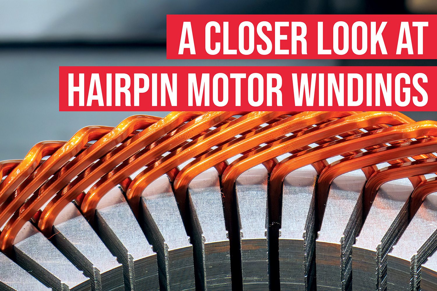
Hairpin motor windings provide an elegant solution to many of the challenges associated with conventional wire windings. As their name suggests, these windings are formed from short, robust copper segments bent into a hairpin-like shape. These pre-formed segments are then directly inserted into the stator slots.
Crucially, hairpin conductors can be precisely sized to fit the stator slots, or vice versa, enabling a significantly higher packing factor, typically around 70%. This improvement is achieved without the undue risk of insulation damage during insertion, a common concern with large conventional wires. Once inserted, the ends of these hairpin segments are bent and welded together to form a complete winding circuit.
The inherent robustness of a single, stout hairpin conductor is a distinct advantage. While skin effect still dictates limits on individual hairpin thickness, engineers can mitigate this by utilizing rectangular cross-section hairpins. Manufacturers like MWS offer rectangular magnet ‘wire’ up to approximately 10 mm wide, achieving a total cross-section of 66 mm², nearly double that of a 6.6 mm round wire. This allows for greater current carrying capacity within the constraints of skin depth.
Concentrated vs. Distributed Windings in Hairpin Motors
Another critical consideration in motor design is the winding arrangement’s impact on torque ripple and overall performance. Two primary structures exist: concentrated and distributed windings.
In a concentrated winding configuration, each pole per phase has a single coil (e.g., six coils in a 2-pole, 3-phase motor). While concentrated windings can lead to very compact motors for a given power output and are often less expensive to manufacture, they suffer from high torque ripple and produce a trapezoidal back electromotive force (EMF) waveform. This makes precise inverter control of stator currents more challenging and results in higher harmonic heating losses across the inverter-motor circuit. Consequently, this structure is rarely, if ever, employed in demanding EV traction applications.
Conversely, distributed windings involve splitting each pole into several coils that overlap across multiple stator slots. This configuration yields much smoother torque output, a more desirable sinusoidal back EMF waveform, and a superior distribution of losses. Although distributed windings may sometimes incur higher total copper losses due to the increased amount of copper, their performance benefits make them ideal for EV applications. Notably, the inherent stiffness of hairpin conductors makes them difficult to bend into the tight radii required by concentrated windings, thus mandating a distributed structure for hairpin motor windings.
The Intricate Process of Joining Hairpin Segments
While hairpin motor windings offer clear advantages in copper density, their primary complexity lies in the manufacturing process, particularly the joining of numerous individual segments. A typical stator can require dozens, or even hundreds, of hairpins to form a complete motor winding coil.
The initial step, often performed before insertion, involves stripping the insulation from the ends of each hairpin segment. Depending on the insulation type, this can be achieved using heat, a laser, chemicals, or abrasive methods. Heat stripping, often through dipping hairpin ends into molten metal or salt baths, allows for batch processing but risks heat damage to insulation near the stripped ends, requiring careful design or subsequent potting.
Laser stripping offers precision, minimal heat-affected zones, and compatibility with various insulation types, even cleaning the copper underneath. However, it incurs higher capital and operational costs due to individual processing and laser electrical efficiency. Chemical stripping, suitable for specific insulation types, also allows batch processing but carries similar risks of insulation damage near the stripped areas.
Abrasive stripping, typically using a sanding belt, is a popular and versatile method. It effectively removes all types of magnet wire insulation, offers significantly lower capital and operational costs than laser stripping, and eliminates the risk of damage beyond the stripped ends. Though each hairpin must be processed individually, the cycle time is typically a fraction of a second, making it an efficient overall process.
Precision Insertion, Bending, and Connection
Following insulation stripping, one or more hairpins are precisely pressed into their respective insulation-lined stator slots, depending on the required coil turns. The stripped ends are then bent to meet the subsequent hairpin in the chain. This bending process must be carefully controlled, as excessive force can damage the insulation. Therefore, the hairpin’s cross-sectional area and the required bend angle must be meticulously designed to ensure reliability.
Once bent to the correct angle, the hairpin ends are physically and electrically bonded. Several methods exist, each with distinct advantages and disadvantages. Soldering, while relatively simple, results in a low-strength joint and necessitates flux application, which then requires subsequent removal. Brazing, a hotter variant of soldering, also requires flux and filler metal but produces a much stronger joint, often exceeding the base metal’s strength.
Welding remains the most prevalent joining method. Resistance welding, or spot welding, involves pressing two hairpin ends together with considerable force while delivering a massive pulse of current through them to induce fusion. However, copper’s excellent thermal and electrical conductivity demands currents easily in the kiloampere range for effective spot welding of these sized components. This makes it challenging for high-volume manufacturing.
TIG (Tungsten Inert Gas) welding or brazing of just the top of the joint presents a more practical and proven method. This technique has been reliably and cost-effectively used for assembling conventional automotive alternators for many years. Another option is laser welding, a moderately exotic method known for its speed, flexibility in repositioning for different designs, and ability to produce high-quality, low-porosity joints. However, laser welding involves high upfront capital costs and significant operational expenses, primarily due to the poor electrical efficiency of lasers and the reflective nature of metals. For a comprehensive overview of laser welding hairpins, the International Journal of the Society of Materials Engineering for Resources offers valuable insights.
The final stage in the conventional hairpin assembly process involves re-insulating the newly welded ends. Optionally, potting these joints further enhances their durability and integrity, especially critical for high-speed motor operation.
The Next Horizon: Continuous Hairpin Motor Windings
The intricate multi-step process of conventional hairpin stator manufacturing has driven intense research into more streamlined approaches. This has led to the development of what are variously termed ‘wave,’ ‘continuously formed,’ or ‘flow’ hairpin windings. The fundamental premise of these buzzword-rich technologies is to preform an entire coil, or even a complete winding structure, as a single unit.
This preforming typically occurs on a tapered mandrel, sometimes colloquially referred to as a ‘sword.’ The taper facilitates easy unloading of the preformed winding onto a segmented belt. This belt precisely fixes each hairpin at the correct distance while the structure is rolled into a cylinder on an arbor equipped with fingers under each hairpin. These fingers can then push the hairpins outwards.
The arbor is subsequently inserted into the stator, aligning its fingers with the stator slots. The fingers then extend to press the hairpins directly into their designated slots. While this concept appears elegant, its implementation involves significant engineering challenges, where the ‘devil is truly in the details.’ This continuously formed hairpin process represents a radical departure from both conventional hairpin winding and traditional wire winding manufacturing methods.
While the initial capital costs for these new manufacturing methodologies are subject to ongoing debate, the continuously formed process appears to offer an overwhelming advantage in assembly time and per-unit cost. This makes it a strong contender for the future of hairpin motor windings in EV production, promising greater efficiency and scalability.
Frequently Asked Questions About Hairpin Motor Windings
What are hairpin motor windings?
Hairpin motor windings are a type of stator winding made from pre-formed, stout copper segments shaped like hairpins. These segments are inserted directly into the stator slots and then joined, typically by welding, to form the complete winding circuit. They are designed to maximize copper fill in electric vehicle (EV) traction motors.
How do hairpin windings improve EV motor efficiency?
Hairpin windings significantly improve efficiency by achieving a higher slot-fill factor, typically around 70%, compared to 55% for traditional wire windings. This allows more copper to occupy the stator slots, reducing resistance losses, enhancing power density, and improving thermal management in EV traction motors.
What are the main challenges in manufacturing hairpin windings?
The primary manufacturing challenges for hairpin windings involve the precise stripping of insulation from many hairpin ends, followed by complex bending and joining processes. Welding methods, such as resistance, TIG, or laser welding, are critical but require high precision, specialized equipment, and careful management of copper’s conductive properties.
Can hairpin windings use concentrated designs?
No, hairpin windings typically cannot use concentrated designs. The inherent stiffness of the stout hairpin conductors makes it difficult to bend them into the tight radii required for concentrated windings. As a result, hairpin motor windings are almost exclusively configured as distributed windings, which offer smoother torque output and better loss distribution.
What is the ‘skin effect’ and how does it relate to hairpin design?
The ‘skin effect’ is an electrical phenomenon where alternating current tends to flow near the surface of a conductor as frequency increases, effectively reducing the conductor’s cross-sectional area and increasing resistance. In hairpin design, engineers must consider skin depth when determining hairpin thickness, often opting for rectangular cross-sections to maximize current flow without exceeding effective skin depth.
What is the future outlook for hairpin motor windings?
The future for hairpin motor windings is promising, particularly with the development of ‘continuous hairpin winding’ processes. These innovations aim to significantly reduce assembly time and per-unit cost by pre-forming entire winding structures. This streamlining of manufacturing is expected to make hairpin technology even more competitive and widespread in next-generation EV traction motors.
How do hairpin windings compare to traditional round wire windings?
Hairpin motor windings offer a higher slot-fill factor (70% vs. 55%), leading to better power density and efficiency. However, traditional round wire windings are more flexible in terms of gauge and turns, benefit from over a century of manufacturing experience, and are generally simpler to wind automatically. Hairpins excel in high-power EV applications where maximizing copper content is crucial, despite their complex manufacturing.